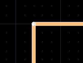
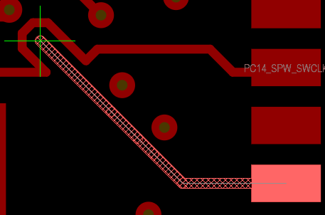
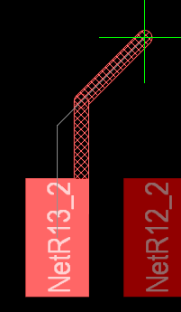
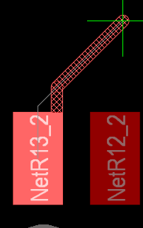
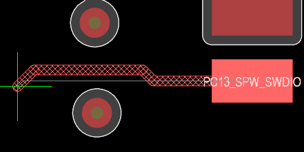
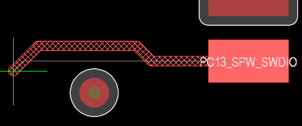
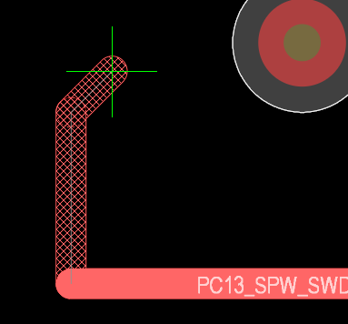
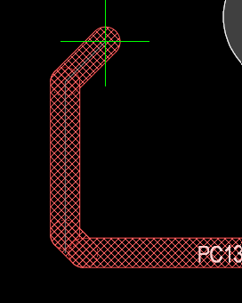
Glossing must be OFF to simplify creating 90 Degree Corners

Ethernet PHY PCB Design Layout Checklist
The total length of each MDI trace should be less than 2 inches, or 2000 mils.
The traces should be lengthmatched within 20 mils for 1G transmissions and within 50 mils for 100M or 10M transmissions.
The number of vias and stubs on the MDI traces should be kept to a minimum.

The traces should be length- matched within . . .
20 mils for 1G transmissions
50 mils for 100M or 10M transmissions.
Also see Gemini AI: https://g.co/gemini/share/ee650e8e10c5
That's it !
See . . .
Using SDRAM vs. DDR RAM in Your PCB Design | Blog | Altium Designer
If you are looking for professional Altium Library design services and have a budget that can support the service then I highly recommend taking a look at . . .
Nine Dot Connects - Library Services
If you have a limited budget and like to do things yourself then I recommend you take Parts for free test drive.
Link to Parts https://pcbparts.blogspot.com/p/welcome.html
Parts is a Scalable Database Library Managment Solution for Altium users.
Parts can be used to quickly create and manage an Access or MySQL Database Library.
To request technical support or a Free Parts online demonstration contact me at Parts.
Link: Contact Parts
Interactive Routing Options - Online Altium (Login Required)
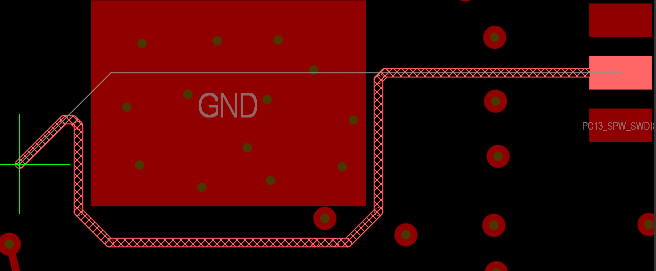
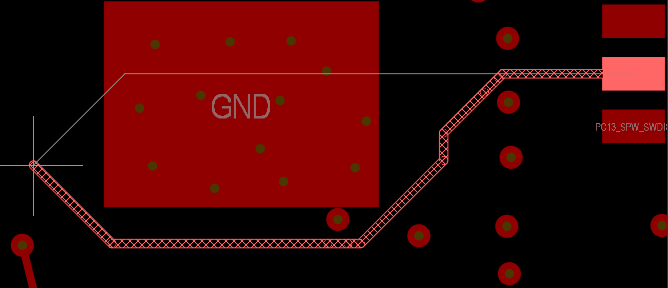
Gloss Effort (Routed) and Gloss Effort (Neighbor).
You may think of Gloss as a postprocessor: after the trace is put in and conflicts resolved, it straightens the result to get rid of corners and other uglies.
If it is Off, uglies are preserved, if Weak - the geometry of the trace mainly preserved, just locally smoothed, if Strong - the trace is made pretty much as short as possible.
See the pictures. Thin white line in all cases shows the trace as it was initially put in, then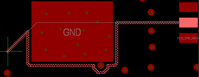

Design > Layer Stack Manager > Menu Back Drills


Customer's Requirements for 0.5mil Length matched Signals within the pairs.
Example
Sawtooth settings based on 6mil / 6mil (trace / gap) Diff Pair

Tip:
You have to select the type of tuning before you start tuning a net.
Hit Tab Key before you start the length matching
Thank you Wayne :)
Example six layer board with Corrupted Mid Layer IDs.
.Layer_ID and .Layer_Name
Example . . . Corrupt Mid Layer IDs
The Fix . . .
Backup the Project Design Files using Project > Project Packager
Open the PcbDoc . . .
Import Changes from Project to Update the Netlist and Design Rules in the PcbDoc.
Run DRC checks, take note of any reported errors.
Create and open a Copy of the PcbDoc in the project.
Design > Layer Stack Manager
Export Stackup as CSV, then include Impedance Screen Captures in Excel.
Delete all Mid Layers from the Corrupt Stackup.
Then add Mid Layers as needed.
Save Stackup to the PcbDoc, then check Mid Layer IDs and Layer Names.
Example Corrected Mid Layer IDs.
Design > Layer Stack Manager
Enter Material Thickness and Impedances as needed.
Save the fixed Stackup to the copy of the PcbDoc
Copy each Mid Layer from Original PcbDoc to Copy of PcbDoc.
Suggested Selection Filter Settings for Copying Mid Layers
Show all Mid Layers and use Signal Layer Mode.
Hide the Multi-Layer to avoid Selecting the Board and Board Cutouts.
Copy each Mid Layer from the Original PcbDoc to Copy of PcbDoc.
Use Edit > Paste Special > Check Paste on Current Layer and Keep Net Name.
Edit Design Rules and Fix Trace Width Rules as needed, including Diff Pairs.
Import Changes from Project to update the Netlist and Design Rules in the Copy.
Run DRC checks, take note of any reported errors.
Done !
Microsoft Word - Footprint Expert Surface Mount Families
Use the link above to download the 39 page PDF


That's it
Project > Variants
Check the First Option for Silkscreen
Check Both Options for Solder Paste

That's it !
C:\Users\rjcle\AppData\Local\TempReleases
Open the Snapshot Folder and Drill Down . . .
That's it !
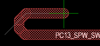
Example - Donut Shaped Room with Height Constraint
Height Constraint using Keep Objects Outside
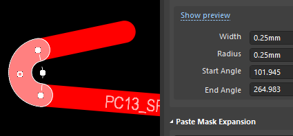
Create two Arcs with Crosshairs.
Draw Rectangular Room, ignore self-intersecting warnings while drawing the polygon. Then Edit Polygon Room Vertices to form joined 90 degree Arcs using Snap to Lines and Arcs.Notes:
Height Constraint Syntax - AsMM(Height) > 0.6
Height Constraint - Online DRC does NOT work (bug ?)
Height Constraint - Batch Mode DRC Check works.
Use Shift + Space Bar to Pull Lines to Arcs.


