Length Tuning Enhancements | Online Documentation for Altium Products:
The length tuning accordion is nice feature added in AD14.3.
The easiest way I have found to explode the accordion is to select the Track > Right Click > Unions > Explode Length Tuning.
Exploding an Accordion
"A length tuning accordion, being a union, is a group object - comprised of primitive track and/or arc segments. As with other group objects, such as components, coordinates, dimensions and polygons, a length tuning accordion object can be 'exploded'. In other words, it can be converted into its constituent free primitives, which can then be modified independently. To do so, use the Explode Length Tuning command, available from the main Tools » Convert sub-menu, or the right-click Unions sub-menu." Source Altium.
'via Blog this'
Showing posts with label Net Lengths. Show all posts
Wednesday, July 30, 2014
AD14.3 Length Tuning Enhancements
Friday, July 18, 2014
Net Lengths - AD14.3.13
Schematic and PCB to demonstrate NET lengths in Altium version AD14.3.13.
Download Altium Project File
Click on images to view.

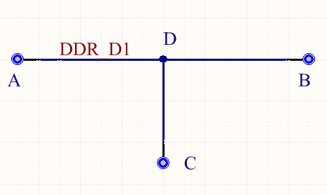
Using three single pin components (A,B,C) with net name (DDR_D1).
PCB layout with grid set for 100 mil.
A to D = 400mil
B to D = 300mil
C to D = 200mil
A to B = 700mil
A to C = 600mil
B to C = 500mil
Total routed length on single layer = 900mil
Using the PCB Panel > Nets
The total routed Net length of 900 mils is shown correctly.
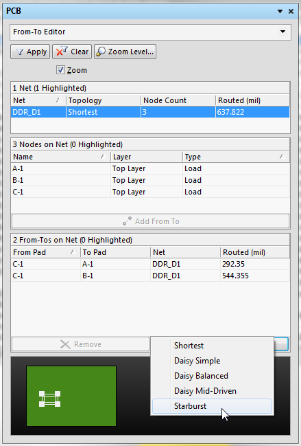
Using the PCB Panel > From- To Editor
The routed length from point A to B of 700 mils is shown correctly.
Let's make things a bit more interesting by adding a via at point 'D'.
Checking PCB Panel > Nets
The total routed length of 900 mils is shown, note the stub length of the via is not included.
Next move the routed segment 'B to D' to the bottom layer and delete the 'C to D' segment.
Using a simple 4 layer stack up (66 mil thick)
Checking PCB Panel > Nets > length of 764 mils is shown.
The via length was accounted for, this is a new feature in AD14, nice !
However as shown below the 'From -To Editor' does not account for via length.
Click on image to view
There is a 64 mil difference.
For high speed designs you may want to account for the via lengths.
The via length data is stale and is not updated as you edit the design. This can be observed by placing a track from 'B to D' on Mid-Layer 1 and a track on Mid-Layer 2 from 'C to D'.
Checking PCB Panel > Nets > routed Net Length of 943 mils is shown.
Next delete the 'C to D' track segment.
Checking PCB Panel > routed Net Length of 743 mils is shown. This length is not correct, the length should be 722 mils.
Now drag the track from 'A to D' then put it back and note the PCB panel updates to 722 mils.
Sticky dashed lines
To get rid of the sticky dashed line left behind by the 'From-To Editor' open the PCB Panel > Nets > Click anywhere in the PCB > Press the End key.
Net length Measurements
Menu > Reports > Measure Selected Objects.
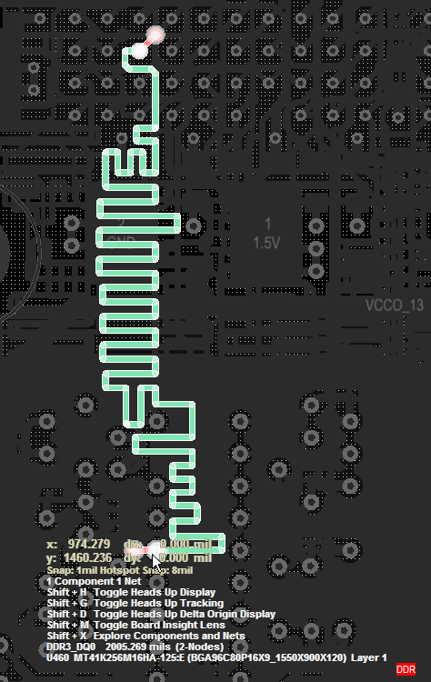
This length 2.005 Inch does not include the selected vias in both AD14.2.5 and AD14.3.13
Compare AD14.2.5 and AD14.3.13
AD14.2.5 Headups Display length = 2005 mils (No VIA Length)

AD14.2.5 PCB Panel length = 2005 mils (Vias NOT Included)
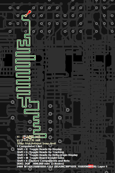
AD14.3.13 Headups Display length = 2090 mils (Includes 2 VIAs)

AD14.3.13 PCB Panel 'Nets' length = 2090 mils (Includes 2 Vias)
AD14.3.13 PCB Panel 'From-To Editor' length = 2005 mils (Does Not Include Vias)
Differential Pairs
Differential pair lengths shown in the 'From To Editor' are also incorrect.
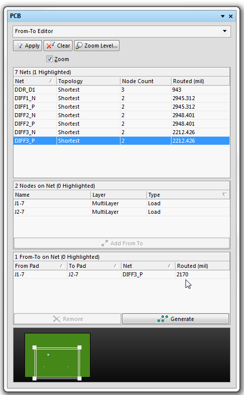
As shown below the measured length is 2212 (correct) and the 'From To Editor' length is 2170 (wrong - does not include VIAs).

Reports > 'Measure Selected Objects' = 2212 (correct)
Conclusion:
AD14.3.13 includes via lengths in the Head Up Display and PCB Panel 'Nets', but NOT in the 'From-To Editor'.
The Reports > 'Measure Selected Objects' does not include the selected vias in the measured length data.
These differences maybe significant for high-speed designs. Depending on the timing requirements of your design you may need to go to great lengths (pun) to ensure you have properly matched length nets.
See Bug Crunch #137 - Altium
See Bug Crunch #960 - Altium
See Bug Crunch #4601 - Altium
That's it.
Download Altium Project File
Click on images to view.

Using three single pin components (A,B,C) with net name (DDR_D1).
PCB layout with grid set for 100 mil.
A to D = 400mil
B to D = 300mil
C to D = 200mil
A to B = 700mil
A to C = 600mil
B to C = 500mil
Total routed length on single layer = 900mil
Using the PCB Panel > Nets
The total routed Net length of 900 mils is shown correctly.
Using the PCB Panel > From- To Editor
The routed length from point A to B of 700 mils is shown correctly.
Let's make things a bit more interesting by adding a via at point 'D'.
Checking PCB Panel > Nets
The total routed length of 900 mils is shown, note the stub length of the via is not included.
Next move the routed segment 'B to D' to the bottom layer and delete the 'C to D' segment.
Using a simple 4 layer stack up (66 mil thick)
Checking PCB Panel > Nets > length of 764 mils is shown.
The via length was accounted for, this is a new feature in AD14, nice !
However as shown below the 'From -To Editor' does not account for via length.
Click on image to view
There is a 64 mil difference.
For high speed designs you may want to account for the via lengths.
The via length data is stale and is not updated as you edit the design. This can be observed by placing a track from 'B to D' on Mid-Layer 1 and a track on Mid-Layer 2 from 'C to D'.
Checking PCB Panel > Nets > routed Net Length of 943 mils is shown.
Next delete the 'C to D' track segment.
Checking PCB Panel > routed Net Length of 743 mils is shown. This length is not correct, the length should be 722 mils.
Now drag the track from 'A to D' then put it back and note the PCB panel updates to 722 mils.
Sticky dashed lines
To get rid of the sticky dashed line left behind by the 'From-To Editor' open the PCB Panel > Nets > Click anywhere in the PCB > Press the End key.
Net length Measurements
Menu > Reports > Measure Selected Objects.
This length 2.005 Inch does not include the selected vias in both AD14.2.5 and AD14.3.13
Compare AD14.2.5 and AD14.3.13
AD14.2.5 Headups Display length = 2005 mils (No VIA Length)

AD14.2.5 PCB Panel length = 2005 mils (Vias NOT Included)
AD14.3.13 Headups Display length = 2090 mils (Includes 2 VIAs)

AD14.3.13 PCB Panel 'Nets' length = 2090 mils (Includes 2 Vias)
AD14.3.13 PCB Panel 'From-To Editor' length = 2005 mils (Does Not Include Vias)
Differential Pairs
Differential pair lengths shown in the 'From To Editor' are also incorrect.
As shown below the measured length is 2212 (correct) and the 'From To Editor' length is 2170 (wrong - does not include VIAs).

Reports > 'Measure Selected Objects' = 2212 (correct)
Conclusion:
AD14.3.13 includes via lengths in the Head Up Display and PCB Panel 'Nets', but NOT in the 'From-To Editor'.
The Reports > 'Measure Selected Objects' does not include the selected vias in the measured length data.
These differences maybe significant for high-speed designs. Depending on the timing requirements of your design you may need to go to great lengths (pun) to ensure you have properly matched length nets.
See Bug Crunch #137 - Altium
See Bug Crunch #960 - Altium
See Bug Crunch #4601 - Altium
That's it.
Friday, September 13, 2013
Excel - Conditional Formatting for Matched Net Lengths
Below is an example of using Green / Red (Go / No-Go) Conditional Formatting in Excel for checking matched trace length requirements.
Example
Example
Saturday, July 6, 2013
Splitting Net Names
If you are using Excel 2007 or higher you can use the 'Text to Column' command to split Net names or other delimited text.
Shown below is an example which splitting the text in column A into 3 columns.
Click on images to view.
Why split ? To sort, then concatenate.
Shown below is an example which splitting the text in column A into 3 columns.
Click on images to view.
Why split ? To sort, then concatenate.
Wednesday, July 3, 2013
Net Length Analysis
Shown below are good routing examples for Net Length Analysis.
The A to B segment is made of a two tracks, the mid point connection is easy to find.

Both Examples above are Good.
BAD Routing example below for Net length Analysis.
AB segment is made of a single track, the mid point connection can NOT be found.

Where does the vertical section intersect the A to B segment ? There is a bit more complexity involved. For example let look at another case below.
Again A to B is single trace segment which is intersected by C. What's the distance from A to C, and B to C ?
Determining the 'To From' lengths will be simplified if there are 3 trace segments as shown below.
Using Altium's PCB Panel and From-To feature with a Starburst Pattern or Daisy Simple, we can display the lengths of the segments from A to C and from B to C.
Let's look at how we can mess up this From to measurement.
As shown below a via has been added and the traces do not meet in the middle of the via.
The measurements are now wrong.
Now, Let's do it right.
As shown below the line segments now all meet at the center of there intersections.
The grid shown above is 50 mils.
Now the measurements are correct,

The A to B segment is made of a two tracks, the mid point connection is easy to find.

Both Examples above are Good.
BAD Routing example below for Net length Analysis.
AB segment is made of a single track, the mid point connection can NOT be found.

Where does the vertical section intersect the A to B segment ? There is a bit more complexity involved. For example let look at another case below.
Again A to B is single trace segment which is intersected by C. What's the distance from A to C, and B to C ?
Determining the 'To From' lengths will be simplified if there are 3 trace segments as shown below.
Using Altium's PCB Panel and From-To feature with a Starburst Pattern or Daisy Simple, we can display the lengths of the segments from A to C and from B to C.
Let's look at how we can mess up this From to measurement.
As shown below a via has been added and the traces do not meet in the middle of the via.
The measurements are now wrong.
Now, Let's do it right.
As shown below the line segments now all meet at the center of there intersections.
The grid shown above is 50 mils.
Now the measurements are correct,

Friday, May 25, 2012
Design Secrets - Video Tips
Subscribe to:
Posts (Atom)