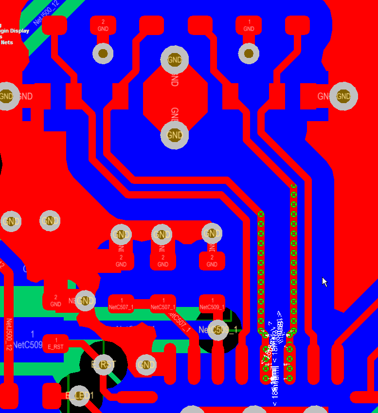
http://bugcrunch.live.altium.com/#Bug/4651
This bug was found in AD14.3.14 (latest release).
Note AD14.2.5 Does not have this problem.
Most likely this bug was introduced into AD14.3.14 while making these enhancements.
Source: http://techdocs.altium.com/pages/viewpage.action?pageId=235578
Note the origin data error will be passed to the pick and place file data.
Steps to re-create the bug:
Download and Import this PADs ascii file INDC3225X280N.asc in to Altium using the import wizard.
Then make pcblib library.
As shown below the pcblib file created from the pcbdoc has an origin offset.
Step by Step:
Import the PADs ASCII file at the link provided above.
click on images to view

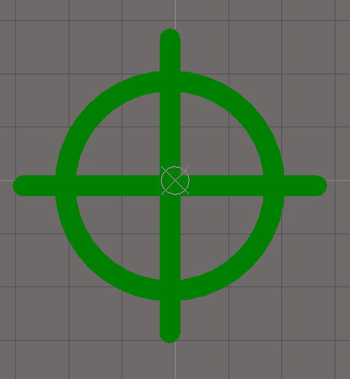
After importing the PADS ASCII file, zoom to the center of the target (crosshairs) and note that the origin is correctly centered in the target.

Also a quick check of the pads properties shows the pads are properly centered about the origin. As shown below the left pad is located at X -1.47mm, Y 0mm

Also the right pad is correctly located at X 1.47mm, Y 0mm
So far everything is correct.
Now let's create a pcblib from the imported PADs ASCII file (the Altium pcbdoc) and zoom in to view the origin in the PcbLib.
As shown below there is an offset error in the origin.
This is serious flaw for anyone who is importing PADs asc data and generating Altium library parts.
This incorrect origin data will be passed to the pick and place file data.
Also the origin error will adversely affect part placement base on the part's origin.
Checking the Left and Right Pad X & Y properties also shows there is and offset error.
Left pad X -1.4827mm, Y -0.0127mm

and the right pad X 1.4573mm, Y -0.0127mm

Work-arounds:
- Manually move the origin in pcblib to center of the target (crosshairs).
- Select Edit > Set Reference > Center
Summary:
Be aware that when importing PADS ASCII data that until this bug is fixed you may need to move the origin in the pcblib files generated after using the import wizard and creating pcblib libraries.
If you have an interest in seeing this bug fixed, cast your vote at:
http://bugcrunch.live.altium.com/#Bug/4651

That's It
If you have an interest in seeing this bug fixed, cast your vote at:
http://bugcrunch.live.altium.com/#Bug/4651
That's It