Thursday, December 31, 2015

Design Import Changes

With a clearance rule defined in the schematic, I'm stuck in an endless change loop.

A workaround can be found below.


Problem:

I have a rule with ClassName "50R" in the schematic.


click on images to view
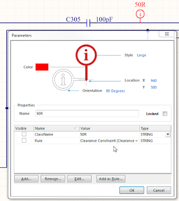


Step 1. Select Design > Import Changes


Step 2. ECO


Step 3. Execute Change, Results Check and Done


Repeat Step 1, 2, and 3.  This is an endless loop


What's going on ? 

What am I doing wrong ?


Maybe there's an option that needs to be toggled.


Workaround:

After the endless loop starts, I create the rule in the PcbDoc.


I typically name the Clearance Rule to something relevant.


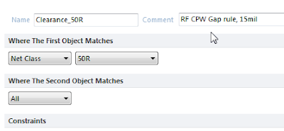
Example, Clearance_50R
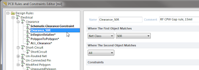


Leave a useful comment in the rule.


Tip: Don't use right click and duplicate the existing schematic rule, because your new rule will be associated with the schematic rule.  If you delete the schematic rule your new rule will also be deleted, you need to create a new rule.


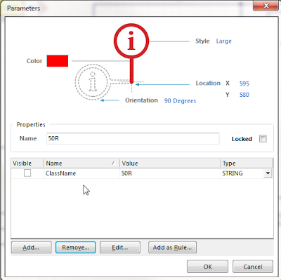
Delete the clearance rule in the schematic.
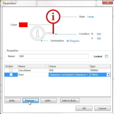


Leave the ClassName parameter in the schematic.


Compile the project and select Design > Import Changes . . . 
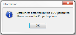


No more endless loop !

The downside to using this workaround is that the rule must be stripped out of the schematic.

It would be nice to keep the rule in the schematic, without the being stuck in the loop.


Please leave a comment If you have a better solution.


That's It !

Monday, December 28, 2015

AD16.0.6 Outjob Not Backward Compatible

AD16 Outjob - Fab Drawing may not be backward compatible with AD15 and earlier.


AD16

click on image to view


AD16 was simplified to Include Surface mount components.


AD15.1.15


click on image to view


AD15 and earlier have options to include Top, Bottom and Double sided components.


AD15 Example:


Sheet 2 of my fab notes displayed a Hard Gold Window in AD15 and earlier


AD16 Example: (missing data from Mechanical Layer 22).

The Mechanical Layer 22 (Hard Gold) data was embedded in a footprint.


The AD15 Outjob 

Configuration6_Name8=OutputConfigurationParameter8

Configuration6_Item8=IncludeBottomLayerComponents=False|IncludeMultiLayerComponents=False|IncludeTopLayerComponents=True|IncludeViewports=True|Index=1|Mirror=False|Name=Hard Gold Window|PadNumberFontSize=14|Record=PcbPrintOut|ShowHoles=False|ShowPadNets=False|ShowPadNumbers=False|SubstituteFonts=False


The AD16 Outjob


Configuration6_Name8=OutputConfigurationParameter8

Configuration6_Item8=IncludeBottomLayerComponents=True|IncludeMultiLayerComponents=True|IncludeTopLayerComponents=True|IncludeViewports=True|Index=1|Mirror=False|Name=Hard Gold Window|PadNumberFontSize=14|Record=PcbPrintOut|ShowHoles=False|ShowPadNets=False|ShowPadNumbers=False|SubstituteFonts=False


AD16 Workaround:


Under Include Components enable Through-Hole


The footprint with Hard Gold has regions on Mech Layer 22 and has Through Holes. Apparently AD16 treats parts a little differently than AD15 and earlier did.

That's it


Sunday, December 20, 2015

SunStone DFM Rules for Altium

By downloading and using these Sunstone specific rule sets you can have confidence that your board can be built by Sunstone without manufacturing difficulties or unnecessary delays.

Altium PCB Design Rules:


'via Blog this'

Thursday, November 5, 2015

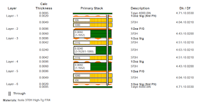
Custom Stackup

How to create a custom Stackup.

Most stackups are created using Build-Up or Layer Pairs.


To enter the stackup shown below the Custom option needed to be used.

click on image to view


Note the dielectric material between layer 3 and Layer 4 is combination of Core a Prepreg.

Select Custom and enter the layer data.


That's It !

Wednesday, October 28, 2015

Drill Drawing - Fab Drawing

How to create a fab drawing with drill charts for blind and through vias.

The example fab drawing shown below has four pages. 

The pages frames and fab notes are not shown in the screen shots to hide confidential data.

Page 1 has the Stackup and Fab notes.

click on images to view


Page 2 has the Drill table and Drill Chart for Layer 1 to 16.


Page 3 has the Drill table and Drill Chart for Layer 1 to 8


Page 4 has the Drill table and Drill Chart for Layer 9 to 16


How it was done.


I used three mechanical layers to display the via symbols above the drill charts.


Note the drill table is placed only once on the Drill Drawing Layer in the design.

Outjob setup for PDF Fab Drawing with three drill tables and charts.


Example for Layer 1 to 8 blind vias.


Choose the drill layers Start = L1 and Last = L8.


Example for Layer 9 to 16 blind vias.


Choose the drill layers Start = L9 and Last = L16.


That's It !

Monday, September 28, 2015

CPW - Polygon's Arc Approximation

The arc approximation for polygons needs to be considered when creating Coplanar Waveguide controlled impedance traces (CPW).

click on images to view

The default Arc Approximation for Polygons is 0.5mil.


Example: The rules call for clearance of 13.6 mils


click on images to view (Gap = Pitch minus Width) = 13.6mils


The measured gap > Report > Measure Primitives


14,7 mils ?


Solution:

Reduce the Arc Approximation for the polygons poured adjacent to the CPW traces.


Re-pour the polygons and measure again.


Result 13.601mils.

Much better !

Sunday, September 20, 2015

PCB: From-To-Editor (AD14 versus AD15)

Looking at the same net using the From-to-Editor

AD14.3.18  (length 1864 mils)


AD15.1.15 (length 1965 mils)


Why the difference ?

AD14.3.18 does NOT account for the length of the vias in the routed path.

AD15.1.15 does account for the length of the vias in the routed path.

This 100 mils is a very significant difference for high-speed designs.

Use AD15.1.15 or higher to account for the vias !

That's It.

Friday, September 11, 2015

Myself and 50+ others have voted on an idea to add all file export options to the Outjob.


"I'm strongly in favour of not just adding ASCII file exports, but any type of file export to the output job. Every time we release a design we have to manually export ASCII files because they are used in the manufacturing process. Sometimes they get forgotten and it leads to delays."  - Altium User Comment


Please support this idea.


Thank you

Monday, September 7, 2015

Nine Dot Connects - The quest for the optimal library

"There are fundamentally 2 library types out there – symbol centric and database library. Symbol centric libraries have been around since the beginning of EDA tools; however, the most efficient method is the database library. In addition to symbol and footprint reuse, it is far easier to create and duplicate formats in a database than it is to do so in a symbol centric library."

"Unless the customer or industry upon which the design is being created for requires version control of a library, there is no need for it. Components generally do not change over time."

Link the full article:  Nine Dot Connects » Library Services

'via Blog this'

Wednesday, September 2, 2015

Open *.PCBLIB or *.SCHLIB Files - Bug

The bug described below applies to AD14 and AD15.

Altium was closed and I right clicked on a *.PCBLIB or *.SCHLIB file in Windows Explorer to Select and Open the library file.  The file did not open.


Altium started up and displayed an invalid license warning.


Work-around:


Open Altium First, then open a *.PCBLIB or *.SCHLIB file.


A second instance of Altium opened and had a valid license, while the other instance did not.


A work-around was found to prevent the second instance of Altium from starting up.


Before opening the *.PCBLIB or *.SCHLIB file from Windows Explorer, first open an existing PCB project, or create a new part using File > New > Library > . . .


The Cause of the Problem:

I was using a roaming license, I work from two locations, my company office and home.


The Fix:

Release the roaming license, use the license, then configure for roaming again.

The mysterious open file from Windows File Explorer bug was exterminated.

That's It !

Tuesday, September 1, 2015

Missing api-ms-win-crt-runtime-l1-1-0.dll

I just started getting this message yesterday every time I started Altium.

The program can't start because api-ms-win-crt-runtime-l1-1-0.dll is missing from your computer. Try reinstalling the program to fix this problem.


"Try reinstalling the program to fix this problem" ?

I can tell you that reinstalling Altium did not fix the problem.

To fix the problem I installed Visual C++ Redistributable for Visual Studio 2015.


For Win 7 64 bit install vc_redistx64.exe


That's It !