Interactive Routing Options - Online Altium (Login Required)
Gloss Effort (Routed) and Gloss Effort (Neighbor).
You may think of Gloss as a postprocessor: after the trace is put in and conflicts resolved, it straightens the result to get rid of corners and other uglies.
If it is Off, uglies are preserved, if Weak - the geometry of the trace mainly preserved, just locally smoothed, if Strong - the trace is made pretty much as short as possible.
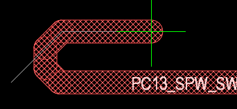
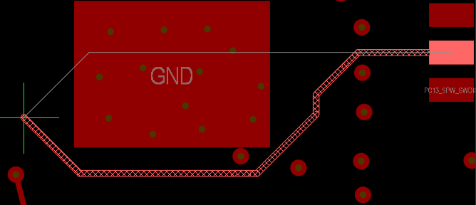
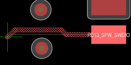
See the pictures. Thin white line in all cases shows the trace as it was initially put in, thenthe first picture shows how it came out after conflict resolution, Gloss (Routed) Off
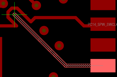
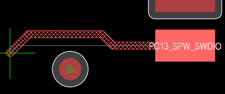
the second - removed sharp corners and small jogs, Gloss (Routed) Weak
the third - tightened it, Gloss (Routed) Strong.
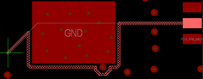
In addition to this, notice that not only the trace being routed may need improvement after conflict resolution, but also its neighbors, if they got pushed:
Again, the same three levels of Glossing are possible, and that is controlled By Gloss Effort (Neighbor) setting.
Automatically Terminate Routing
This is a small option. It controls what happens when during routing you click on a target to complete a connection.
This is a small option. It controls what happens when during routing you click on a target to complete a connection.
The trace to make the connection will be put in regardless of the setting, but after that you will either stay in the Routing command, so further cursor movements will put in more tracks, (Auto Terminate Off), or exit the command, so you can use the cursor to select the start point for the next trace (Auto Terminate On).
Pad Entry Stability
Controls Pad Entry, which is also the responsibility of Gloss (no Pad Entry if Gloss (Routed) is Off)
Controls Pad Entry, which is also the responsibility of Gloss (no Pad Entry if Gloss (Routed) is Off)
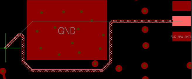
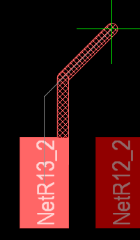
In this picture you see the thin white line showing the trace that was originally put in, and the final result, where Gloss improved the pad entry.
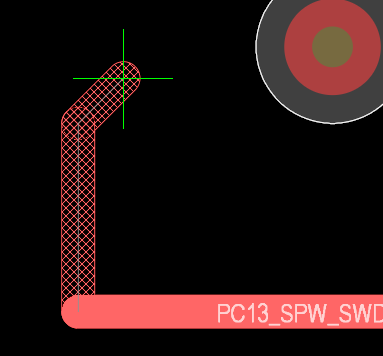
You may not think much of this improvement, but consider also these two cases:

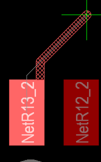
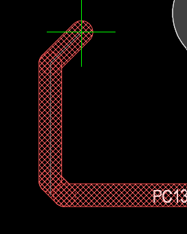
Here keeping the middle entry caused a nasty acute angle at pad edge, and shifting it to the side is probably welcome.
So, Pad Entry Stability setting tells Gloss how close the corner has to be to the pad edge when shifting entry sideways becomes allowed.
At Max it will never shift the entry, and you will get those acutes; at Off it will always shift, and you will always get off-center entry.
You may want to experiment with intermediate values to see which suites you, but be warned that picking different values near Off and near Max will result in pretty much the same behavior.
I would recommend making the choice between Off, Max, and a couple of positions in the middle.
Added Clearance Ratio
This is related to Trace Centering option.
This is related to Trace Centering option.
This option works in an indirect manner: it tries to maintain some extra clearance to the obstacles.
If the trace cannot squeeze between the obstacles, the extra clearance will be reduced by the same amount from both sides, so the trace will be centered between these obstacles.
Otherwise the trace will be put at (normal + additional) clearance from obstacles, so in this case it will be not so much "trace centering" as "preferred clearance".
The value of the additional clearance, is controlled by Added Clearance Ratio.
Otherwise the trace will be put at (normal + additional) clearance from obstacles, so in this case it will be not so much "trace centering" as "preferred clearance".
The value of the additional clearance, is controlled by Added Clearance Ratio.
If the ratio is 1, then additional clearance equals the clearance from the rule, so the router will try try to maintain twice the normal clearance to the obstacles.
The larger the ratio, the harder the router's job will be, and it is not recommended to go much beyond 2.
Miter Ratio
Consider the case when after a click while routing, you make a sharp turn.
Not everyone likes to have those right angles in their traces, which is when the miters come to the rescue - also the responsibility of Gloss.
Here the white thin line starts from the click point, but as you can see, a small portion of the previously committed trace is cut off and a short diagonal segment is inserted.
That's a miter. You can also see miters if you scroll back to the picture demonstrating Weak Gloss.
Miter Ratio controls the length of the miters used by the router. Since miters can be arcs as well as segments, they are defined in terms of "sharpest turn radius" as a multiple of trace width.
Miter Ratio controls the length of the miters used by the router. Since miters can be arcs as well as segments, they are defined in terms of "sharpest turn radius" as a multiple of trace width.
Miter Ratio 1 allows the radius equal to trace width, which can be plainly seen for arcs:
and not so plainly, but still true, for tracks: