Friday, February 24, 2017

Use 32-bit Microsoft Office Apps with Altium

Quoting Microsoft

32-bit Office is recommended for most users

We recommend the 32-bit version of Office for most users, because it's more compatible with most other applications, especially third-party add-ins. This is why the 32-bit version of Office 2013 is installed by default, even on 64-bit Windows operating systems. On these systems, the 32-bit Office client is supported as a Windows-32-on-Windows-64 (WOW64) installation. WOW64 is the x86 emulator that enables 32-bit Windows-based applications to run seamlessly on 64-bit Windows systems. This lets users continue to use existing Microsoft ActiveX Controls and COM add-ins with 32-bit Office.
I know, you are thinking what the heck ! 

You bought a whiz bang 64-bit computer with 64-bit Ops/System and I'm suggesting you install the 32-bit version of Office which includes Excel and Access.


Office 365 Home edition includes Access.
Office 365 For Business includes Access.

The internet and Altium forums are littered with problems that occur after installing 64-bit Office.  And the problems disappear after installing 32-bit versions of Office.

Parts is available in 32-bit and 64-bit versions and both versions can be used with Altium.

32-bit versions of Altium only recognize 32 OBDC database drivers for Access. The workaround for using 64-bit Parts is to install the 32-bit Office 2010 Database Engine. 

Office Compatibility Related Links:

Microsoft Recommends 32-bit Office.
Find which version of Office you have Installed.
Office Installation Error Messages.


Altium Forum Links:

DBLIB EOIeException Error  - Altium Discussion Forum
Excel BOM Template Failures - Altium Discussion Forum
Excel 64-bit BOM Templates Issues.  - Altium Discussion Forum

Idea #8264: Make Altium Compatible with Microsoft 64 bit Office Apps - Altium Forum.


That's it !
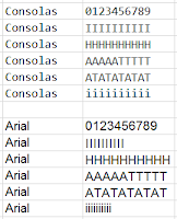
Default Font Types

Want to use a different font than the default 'Times Roman' that ships with Altium ?

Reasons include personal preferences and creating better looking documentation.

Arial and Times Roman are proportional fonts.

Consolas is a monospaced (fixed width font).  All characters are the same width.


Save a copy of your current DXP Preferences before making changes !

To set the default font for designators placed in the schematic.

DXP > Preferences > Schematic > Default Primitives > Designator

click on images to view


Note that the Comment and Designator parameters have an option to override the library primitives (font). 

Check it !


To change existing parts placed in your design use Find Similar . . .


Select Font > Same > Apply


Change Font Type as desired.

Select Project Documents > OK

That takes care of the designators.

As shown below the designators are using Arial and the parameter named 'Value' is using Altium's default Times Roman font.


DXP > Preferences > Schematic > Default Primitives > Parameter


Going forward the fonts in your schematic should follow your DXP Preferences settings.

Repeat the steps above for all Primitives that use Fonts if desired.

The Primitives that use fonts include:

Code Entry
Comment
Harness Connector Type
Hyperlink
Net Label
Note
Pin
Port
Power Object
Sheet Entry
Sheet Symbol Designator
Sheet Symbol Filename
Text String
Text Frame


Tip 1: 

Save your DXP Preferences, you may need to Load them into a newer release of Altium or want to share your preferences with your design team (to get everyone on the same page).

Tip 2:

When selecting a font you should consider what font is installed on other users or your customers computers that you are working with.

Getting -Missing True Type Font- pop up when I open a PCB - Altium Discussion Forums

That's it !

Friday, February 10, 2017

Component Classes

Component classes can be defined in the schematic or the PCB.  To create the component class in the schematic add a parameter to a component, with a name set to ClassName and a value for the class name.

When the design is transferred to the PCB, the defined component classes will be created if the Generate Component Classes option (for User-Defined Classes) is enabled, on the Class Generation tab of the Options for Project dialog.


Tip: 


Select a group of components in the schematic, then use the parameter manager to quickly add a component class to the selected parts. Or use Find Similar and the Properties Panel.


After the schematic has been pushed to the PCB the PCB panel can be used to select component classes.


That's it !

RF Copper Keepouts

Designing copper cutouts using design rules.


Design Rule


Not InNet('*') and IsTrack 

and  

IsVia

After applying above rule


That's it !