Thursday, December 31, 2015

Design Import Changes

With a clearance rule defined in the schematic, I'm stuck in an endless change loop.

A workaround can be found below.


Problem:

I have a rule with ClassName "50R" in the schematic.


click on images to view
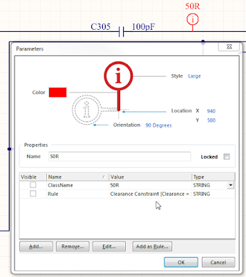


Step 1. Select Design > Import Changes


Step 2. ECO


Step 3. Execute Change, Results Check and Done


Repeat Step 1, 2, and 3.  This is an endless loop


What's going on ? 

What am I doing wrong ?


Maybe there's an option that needs to be toggled.


Workaround:

After the endless loop starts, I create the rule in the PcbDoc.


I typically name the Clearance Rule to something relevant.


Example, Clearance_50R
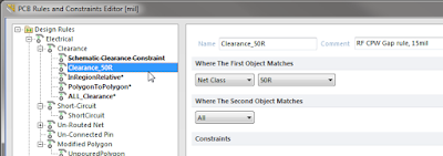


Leave a useful comment in the rule.
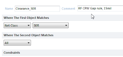


Tip: Don't use right click and duplicate the existing schematic rule, because your new rule will be associated with the schematic rule.  If you delete the schematic rule your new rule will also be deleted, you need to create a new rule.


Delete the clearance rule in the schematic.
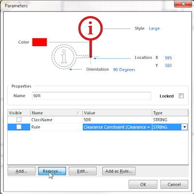


Leave the ClassName parameter in the schematic.
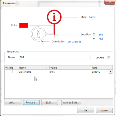


Compile the project and select Design > Import Changes . . . 
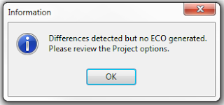


No more endless loop !

The downside to using this workaround is that the rule must be stripped out of the schematic.

It would be nice to keep the rule in the schematic, without the being stuck in the loop.


Please leave a comment If you have a better solution.


That's It !

Monday, December 28, 2015

AD16.0.6 Outjob Not Backward Compatible

AD16 Outjob - Fab Drawing may not be backward compatible with AD15 and earlier.


AD16

click on image to view


AD16 was simplified to Include Surface mount components.


AD15.1.15


click on image to view


AD15 and earlier have options to include Top, Bottom and Double sided components.


AD15 Example:


Sheet 2 of my fab notes displayed a Hard Gold Window in AD15 and earlier


AD16 Example: (missing data from Mechanical Layer 22).

The Mechanical Layer 22 (Hard Gold) data was embedded in a footprint.


The AD15 Outjob 

Configuration6_Name8=OutputConfigurationParameter8

Configuration6_Item8=IncludeBottomLayerComponents=False|IncludeMultiLayerComponents=False|IncludeTopLayerComponents=True|IncludeViewports=True|Index=1|Mirror=False|Name=Hard Gold Window|PadNumberFontSize=14|Record=PcbPrintOut|ShowHoles=False|ShowPadNets=False|ShowPadNumbers=False|SubstituteFonts=False


The AD16 Outjob


Configuration6_Name8=OutputConfigurationParameter8

Configuration6_Item8=IncludeBottomLayerComponents=True|IncludeMultiLayerComponents=True|IncludeTopLayerComponents=True|IncludeViewports=True|Index=1|Mirror=False|Name=Hard Gold Window|PadNumberFontSize=14|Record=PcbPrintOut|ShowHoles=False|ShowPadNets=False|ShowPadNumbers=False|SubstituteFonts=False


AD16 Workaround:


Under Include Components enable Through-Hole


The footprint with Hard Gold has regions on Mech Layer 22 and has Through Holes. Apparently AD16 treats parts a little differently than AD15 and earlier did.

That's it


Sunday, December 20, 2015

SunStone DFM Rules for Altium

By downloading and using these Sunstone specific rule sets you can have confidence that your board can be built by Sunstone without manufacturing difficulties or unnecessary delays.

Altium PCB Design Rules:


'via Blog this'