High Speed Design with xSignals | Online Documentation for Altium Products:
'via Blog this'
Sunday, November 15, 2015
Thursday, November 5, 2015
Custom Stackup
How to create a custom Stackup.
Most stackups are created using Build-Up or Layer Pairs.

To enter the stackup shown below the Custom option needed to be used.
click on image to view
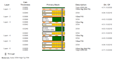
Note the dielectric material between layer 3 and Layer 4 is combination of Core a Prepreg.
Select Custom and enter the layer data.

That's It !
Most stackups are created using Build-Up or Layer Pairs.
To enter the stackup shown below the Custom option needed to be used.
click on image to view

Note the dielectric material between layer 3 and Layer 4 is combination of Core a Prepreg.
Select Custom and enter the layer data.

That's It !
Saturday, October 31, 2015
Wednesday, October 28, 2015
Drill Drawing - Fab Drawing
How to create a fab drawing with drill charts for blind and through vias.
The example fab drawing shown below has four pages.
The pages frames and fab notes are not shown in the screen shots to hide confidential data.
Page 1 has the Stackup and Fab notes.
click on images to view

Page 2 has the Drill table and Drill Chart for Layer 1 to 16.

Page 3 has the Drill table and Drill Chart for Layer 1 to 8

Page 4 has the Drill table and Drill Chart for Layer 9 to 16

How it was done.

I used three mechanical layers to display the via symbols above the drill charts.

Note the drill table is placed only once on the Drill Drawing Layer in the design.
Outjob setup for PDF Fab Drawing with three drill tables and charts.

Example for Layer 1 to 8 blind vias.

Choose the drill layers Start = L1 and Last = L8.

Example for Layer 9 to 16 blind vias.

Choose the drill layers Start = L9 and Last = L16.

That's It !
The example fab drawing shown below has four pages.
The pages frames and fab notes are not shown in the screen shots to hide confidential data.
Page 1 has the Stackup and Fab notes.
click on images to view

Page 2 has the Drill table and Drill Chart for Layer 1 to 16.

Page 3 has the Drill table and Drill Chart for Layer 1 to 8

Page 4 has the Drill table and Drill Chart for Layer 9 to 16


I used three mechanical layers to display the via symbols above the drill charts.

Outjob setup for PDF Fab Drawing with three drill tables and charts.

Example for Layer 1 to 8 blind vias.
Choose the drill layers Start = L1 and Last = L8.

Example for Layer 9 to 16 blind vias.
Choose the drill layers Start = L9 and Last = L16.

That's It !
Thursday, October 8, 2015
Release Notes for Altium Designer Version 14.3.19
Release Notes for Altium Designer Version 14.3.19
Version 14.3.19 was released on Oct 6, 2015
'via Blog this'
Version 14.3.19 was released on Oct 6, 2015
'via Blog this'
Subscribe to:
Posts (Atom)