Saturday, January 28, 2017

Step Model - Altium <> Solidworks

Here are some views in Solidworks for a project I'm currently working on.

AD17.0.9 has a new option to export boards as a Single Part.

click on images to view


As noted above parts can not be relocated in Solidworks when the step model is a single part, that was expected. 

Single parts are useful for defining envelopes, however single parts are not well suited for collaboration when parts need to be moved in Soildworks then and passed back to Altium.

Why the Power Jack and Audio Jack broke up was a bit of mystery, the answer and workarounds can be found in this post.

I also exported the Step Model with all parts (Not Single Part)


As noted above a couple of parts came in to Solidworks with shifted origins. The power jack broke in two pieces and the larger piece went to the upper right corner of the board. The BGA which was at the center of board also headed north east. And the 6 LEDs at lower edge disappeared.


Altium version: AD17.0.9

Solidworks versions: 16 and 17

I downloaded and installed Solidworks FREE 3D Viewer (eDrawings)

I looked at the same board (actually an older version of the board) using eDrawings. I may update the next two screen grabs later for an apples to apples comparison.

Single Part


All Parts


The step models look good in Solidworks eDrawings.

I did not experience the same broken and shifted parts that occurred in Solidworks.

Step Model: CUI P/N SJ-3566AN

You can download the SJ-3566AN.stp model at Digi-Key.


As shown above the step model looks good in Altium (AD17.0.9) 

Export the board with All Parts (Not Single Part)

click on image to view


Next place the exported 3D Body back into the pcb.


Looks good in Altium.

Next Export PCB as Single Part Step Model


Then I placed the exported 3D model into Altium.


No issues found in Altium.


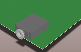
Above is the design and both of the step models in Altium for the SJ-3566AN.stp

Next, using Solidworks FREE 3D Viewer (eDrawings)


Single Part 3D Step Model


Everything looks good in Altium and eDrawings.

Why is the imported step model broken in SolidWorks ?

Here is what's happening:

The first time you import the Step Model from Altium with all of it's parts, life is good, every thing looks right.

Then in Altium move or add few parts, export Step and import Step in Solidworks using the same project folder in SolidWorks, now the wheels start to fall off the bus.

In a nut shell what's happening is during subsequent imports using the same folder Solidworks get's confused if the file names of the parts are the same.

"There's an issue in solidworks that it caches (no way to turn this off) when assemblies are opened and closed and others opened with in the same session that have the same names.

Solidworks (at least in the versions we use), once it opens a part, does not look at absolute paths to same name parts. It just uses whatever was last opened in that session.

The only real way to do clear it is to end the Solidworks session."  Thank you Wayne M.

Workarounds in SolidWorks:

1) Delete all parts in the SolidWorks project folder where the first step model was imported, before importing the same board again.

or

2) Using Pack and Go in SolidWorks a user can rename or add a suffix to all of the parts to avoid these issues.

Related Links:

Reference 1:

"Use Pack and Go, try adding something to the filename (e.g. add suffix "-1"). So that all the inherently different models have different file names."

Reference 2: (more Pack and Go)


Workarounds in Altium:

1) "When you make the Step export from Altium, add a custom suffix, for the next export add a different suffix, you have to keep track of those manually, doesn't matter what they are they just need to be different then SW won't reuse the wrong one from its cache. i like them short, and AD unfortunately does not auto-check the radio button when you put something in the text field, i.e. it is too easy to type the suffix in but not actually add it, nor is it retained so you can keep track.

or

2) "Don't use Step, use the Parasolid Export instead, the file is a fraction of the size and the SW load time is seconds rather than minutes to rebuild the surfaces"


Source: Altium Community Forum: Dennis Saputelli

Thank you Dennis:)


Audio Jack Step Model Source File 'SJ-3566AN.stp' was downloaded from Digi-Key.

The File Header is:

ISO-10303-21;
HEADER;
FILE_DESCRIPTION((''),'2;1');
FILE_NAME('SJ-3566AN','2015-03-11T',('carefree'),(''),
'PRO/ENGINEER BY PARAMETRIC TECHNOLOGY CORPORATION, 2010020',
'PRO/ENGINEER BY PARAMETRIC TECHNOLOGY CORPORATION, 2010020','');
FILE_SCHEMA(('AUTOMOTIVE_DESIGN { 1 0 10303 214 1 1 1 1 }'));

ENDSEC;


That's it !

Saturday, January 21, 2017

Why is my polygon clearance rule ignored?

Why is my polygon clearance rule ignored? - English documentation - The Altium Wiki:

Tip:


Use IsNamedPolygon vice inNamedPolygon

Or 

(ObjectKind = 'Poly') And (Name like 'L1_RF_GND')

With wild cards
(ObjectKind = 'Poly') And (Name like '*L1_RF_GND*')
(ObjectKind = 'Poly') And (Name like '*L05_GND*')

Or

Design > Classes > PolygonClasses then use the polygon class in the Rule.


click on image to view


That's it !

Wednesday, January 11, 2017

Parts DBLib Library - FREE

The FREE Parts DBLib contains everything you need to get an Altium DBLib library up and running in less than 5 minutes.

Did you know ?


You do NOT need to have Access installed to use a DBLIB library in Altium.


Using Altium's DBLib interface you can edit and add parts to an Access database.


Take the challenge and see for yourself that you really can have your own fully functional DBLib library in 5 minutes or less.


Here are the steps to quickly setup and use the Parts DBLib library:


Download Parts DBLib.


Install the Parts DBLib Library in Altium. See Getting Started.


Use Altium's DBlib to edit or add parts to the database.

You are done, you should have a fully functional Altium DBLib library.

If you are looking for a more efficient way to edit and add parts to the database give the Parts Frontend a test drive. 

The Parts DBlib download includes a demo version of the Parts Frontend.  A Frontend application is not required to use an Altium DBLib or SVNDBLIB library.

When using a well designed database Frontend you will spend significantly less time designing library parts, leaving you with more time to design boards.


What Makes Parts Different ?


That's It !

Saturday, January 7, 2017

Component Links - Part 2

Exercise:  How to Create Duplicate Component Links

Related Link: Component Links - Part 1

Create a simple one sheet schematic and PCB. 


Add two components C1 and C2 and push the changes to the PCB.


As shown the schematic and PCB components are linked and in sync'ed.

Next reuse the same schematic sheet for another circuit.


Save the schematic sheet simple_1. 

Then select File > Save Copy As to create sheet simple_2.  


Select Project  > Add Existing to Project > and add sheet simple_2.


Look at C1 and C2 on both sheets and note we have duplicate designators and duplicate unique IDs.


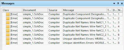
Compile the project and note we have some issues to fix.


Right away we notice the duplicate Designators for C1 and C2.

Let's re-annotate the Designators


Now we have C1,C2,C3,C4

Run the Compiler, Select Project > Compile . . . 


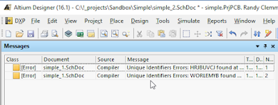
The duplicate designators error are fixed, however we still have unique ID errors.

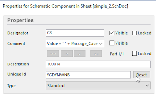
Let's Reset Unique IDs of the Designators for C3 and C4.


Select the symbol's properties and select Reset.


Compile the project and note the unique ID errors are fixed.

Push the changes to the PCB.


Related Links:


Reset Unique IDs

Component Links - Part 1

Upgraded Duplicate UID Correction | Altium Docs

Friday, January 6, 2017

Component Links - Part 1

Component Links in Altium are very handy when used properly. 

However there are ways to get in to trouble if you don't understand how Component Links work and how they become broken or even worst corrupted.


To stay out of trouble do NOT copy and rename a schematic sheet. Instead add a new sheet, copy and paste from an existing sheet to the new sheet then re-annotate the new sheet.  Cut and Paste can be used to reset the unique IDs,

First let's look at how the component links are created.


Suggested Reading:


Edit Component Links | Online Documentation for Altium Products


Suggested Exercise:


Place cap (C5) in a schematic, then look at the properties of C5.


Note the part (symbol) has a unique ID = FQMRRBKU and to the right is a Reset Button.


Obviously your C5's unique ID will be different.


click on image to view


Create a PcbDoc and push C5 to the PCB.


Next a look at the properties of C5 in the PCB


The part has a unique ID = \FQMRRBKU


FQMRRBKU = \FQMRRBKU is the component link for C5.

Again your ID will be something different, however they should be a matched set.


Now in the schematic let's change the Ref/Des from C5 to C6. 


Check the properties of C6 and note the unique ID = FQMRRBKU (same ID).


Now we can import the changes from the schematic to the PCB and using the unique ID Altium will automatically update (change) the Ref/Des from C5 to C6 where ID FQMRRBKU = /FQMRRBKU.


In a nutshell Component Links allow us to re-annotate (change) Reference Designators in the schematic, then push the changes to the originally placed parts the PCB.


Now let the fun begin:


Let's Copy and Paste C6 in the schematic


Let's keep the duplicate C6 and push the changes to the PCB.

Select the PCB > Design Import Changes . . .


Note that Altium is warning us that there are compiler errors.


Let's ignore the warning for now and execute the changes.


Now we have a duplicate a C6 in the PCB.


Let's delete the original (first) C6 which has ID = FQMRRBKU in the PCB.


Let's delete the duplicate (2nd instance) of C6 in the Schematic.


Now in the Schematic I have C6 with ID = FQMRRBKU 


Now in the PCB I have C6 with ID =  \TJABRXVV


So now we have C6 in both the schematic and PCB, however we destroyed the matching unique ID (Component Link).


Another way to break the matched unique IDs is to select Reset button in the symbol's properties.


Let's push the changes from the schematic to the PCB.


Right away Altium warns us that there was a failure to match 1 of 11 components.


We have three options

1 Automatic Matching

2 Manual Matching
3 Cancel

Let's work backwards starting with option 3.


If we select Cancel the Engineering Change Order dialog is displayed.


Note that we can select Validate Changes or Execute Changes.


To cancel without making changes select the Close button.


Next let's look at Option 2, Manual Component Links.


Now we are presented with dialog for Manual matching or un-matching any and all parts in the design.


It's up to you to correctly match the components (you are on your own).


At the bottom of the dialog there are options to Add Pairs Matched By >> 


The default option is by Designator, however there are options to include more constraints i.e. same Comment and Footprint.


If we select Add Pairs Matched By >> Designator, then select Perform Update the results will be the same as if we had selected Automatic Linking (Option 1).


Related Link:


Component Links - Part 2 


That's It !