Steps to create a custom Toolbar Command Button to Run a Script.
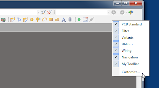
Right Click on and empty space in the menu bar and select Customize . . .
Select Toolbar Tab and Create a New Toolbar
Select the Commands Tab, then [Custom] then New
For Process Select: ScriptingSystem:RunScript
Enter the Parameters, Example:
ProjectName=C:\Altium_RJC\Altium_Central\Scripts\Via Soldermask Barrel Relief\Via Soldermask Barrel Relief.PrjScr|ProcName=Via Soldermask Barrel Relief.pas>Start
Enter a Caption and Description.
Select an existing Altium Command Button or Create your own Button.
AD14 Buttons are installed at:
"C:\Program Files (x86)\Altium\AD14\System\Buttons"
Drag and Drop The New Command Button to your Custom Toolbar
You can also easily add a Hot key (keyboard short cut) to any command button or menu by holding down the Ctrl Key and double clicking the left mouse button.
Example to Export Hyperlynx in AD15
Updated Via Soldermask Barrel Relief (9-11-2013 11-24-56 AM)
PCB fabricators may request permission to apply Soldermask Barrel Reliefs to your tented vias when the via's hole sizes are 18mil or larger in size. Consult with your fabricator as the requirements vary between suppliers.
For more about Soldermask Barrel Reliefs see : Via Barrel Reliefs - PCB Designer Blog
Fabricators specify the barrel reliefs with respect to the via hole size. For example drill hole size + 5mil is typical.
The +5mil soldermask relief accounts for registration and process tolerances.
To Force Complete Tenting
Tenting vias on one side can trap chemicals and fluxes in the via barrels which can corrode away the copper plating in the via barrels. This is a reliability issue.
Reference: Soldermask on via-holes in case of chemical Nickel-Gold surface finish
To update a PCB design from a PcbLib.
Open the *.PcbDoc and the *.PcbLib.
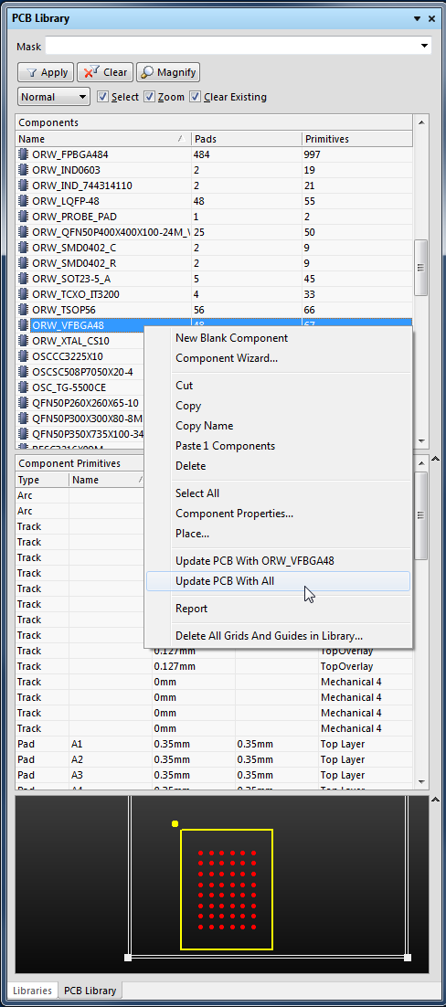
Select a Component in the PCB Library Pane, then Right Click to Update PCB with the selected component.
Or Update the entire PCB with all of the footprints with the same name parts by selecting 'Update PCB with All'.
Typical scenario, you need to update a PCB design and you may not have access to the libraries from which the parts originated.
First create PcbLib from the PcbDoc: Menu > Design > Make PCB Library
Modify the footprints as need then update the PcbDoc from the PcbLib following the steps described above.
Note that the PCB will be immediately updated without going through an ECO and a Report is not generated.
Interactively Routing a Net - English documentation - The Altium Wiki:
"The Interactive Router is able to attempt automatic completion (Auto-Complete) of connections to the target pad, hold CTRL and Left Click to instruct the Interactive Router to attempt to complete the current connection.
This can make routing much faster than placing individual track segments, however, there are some limitations to Auto-Complete feature, as follows:
Start point and target pad are on the same layer The route can be completed in accordance with design rules (provided that routing conflicts are not being ignored).
Auto-Complete is available at any time, and you can even CTRL + Click directly on a pad or connection line to route it, there is no need to select it first.
You can use Auto-Complete on connections that are partially routed as well. To do this, CTRL + Click on the end of the last track segment or the remaining connection line to complete it to the target.
If a connection cannot be auto-completed the tool will return to the last used interactive routing mode."
'via Blog this'


