As my DbLIB record count was approaching about 1000 records I began to wonder if Altium was going to take a big performance hit as my single table database library continued to grow.
I decided to do some limit testing.
I created an dummy Access database table library with > 10,000 parts. I was pleased to see that the Library Panel (parts placement window) was fully populated in a few seconds and very responsive to part searches and part placement.
When designing your Altium DBLib database, you may be tempted to break the table up and spread it across several part type tables such as:
Capacitors
Connectors
Inductors
ICs
Resistors
Other
I suggest you keep all of your parametric data in a single flat table and organize the Library Panel.
This method has a couple of noteworthy benefits. Most importantly by using a single table you can easily prevent users from entering duplicate part numbers into the database.
Another benefit of the single flat table model is that is easier to copy and paste records to create new parts that are similar to existing parts in the table (make like).
When designing a database schema think about what is required in the Bill of Materials.
That's it !
Sunday, December 30, 2012
Saturday, December 29, 2012
Scripts - Reference Manuals
API reference
manuals for Scripting in Altium
TR0138, TR0139, TR0140 and TR0141.
VB Script Reference TR0125
Example Scripts Installation Path:
TR0138, TR0139, TR0140 and TR0141.
VB Script Reference TR0125
Example Scripts Installation Path:
DDR2 SDRAM - Components
Using Altium's ready to use parts can save you hours of design time.
Micron DDR2 SDRAM - Altium Content Store
Component_Management
The Vault is a repository of released re-usable content, it is not a production Product Life Management (PLM) tool. The vault is a design life-cycle tool.
Once a product leaves the design phase and goes into volume production, the manufacturing side of the company will typcially use a PLM tool, such as Agile or Arena.
Are you using Altium's Vault Services? Comments welcome.
Here are some interesting comments about using Altium's Vault
Once a product leaves the design phase and goes into volume production, the manufacturing side of the company will typcially use a PLM tool, such as Agile or Arena.
Are you using Altium's Vault Services? Comments welcome.
Here are some interesting comments about using Altium's Vault
Wednesday, December 26, 2012
Saturday, December 22, 2012
Vault-Driven Electronics Design - English documentation - The Altium Wiki
Vault-Driven Electronics Design - English documentation - The Altium Wiki: " with key design and management practices, to fuel a high-quality, high-yield design flow – empowering your design team to design with freedom in a highly-secure environment. A"
'via Blog this'
Saturday, December 15, 2012
Altium Gaining Market Share
Altium is Gaining Market Share
Recent surveys have Altium at ~ 39% of the market share.
Printed Circuit Design & Fab Magazine Online:
Recent surveys have Altium at ~ 39% of the market share.
Printed Circuit Design & Fab Magazine Online:
Wednesday, December 12, 2012
PCB - Differential Pairs
Tuesday, December 11, 2012
Monday, December 10, 2012
Google Drive - SyncToy
I use Google Drive and SyncToy to keep files synchronized and backed up.
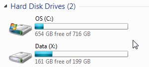
Partition the C: Drive and Create X: Drive.
Create X:\Google Drive
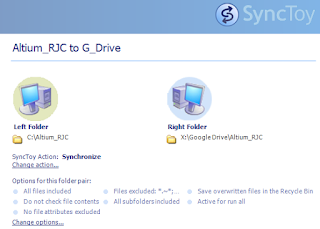
Create SyncToy Folder Pair
Example: Set SyncToy Options
I like to exclude Altium History and Access Lock Files *.~*;*.ldb
Google Drive gives me easy access to my files from anywhere via the internet. You can also choose to share files or not to share files.
Google Drive is great for synchronizing files between remotely located PCs, such as work and home or a workstation and mobile devices.
Google starts you off with 5 GB of free space and offers very affordable upgrades.
I use SyncToy for local drives and intranet backups.
For trouble free drag and drop file operation I recommend partitioning the C: drive. It is too easy to accidentally move files using drag and drop when both folders are in the C: drive. Creating a partition solves the copy vice move files problem.
Create X:\Google Drive
Create SyncToy Folder Pair
Example: Set SyncToy Options
I like to exclude Altium History and Access Lock Files *.~*;*.ldb
Tuesday, November 20, 2012
OutJob - Combine PDFs
PDFs can be combined in OutJobs.
The order of the combined outputs is controlled by the order of selection, see mouse pointer in the screen shot below.
Friday, November 16, 2012
Sheet References
In Altium Sheet to Sheet References are referred to as Port Cross References.
For hierarchical designs you would NOT use Port Cross References since all references lead to the top hierarchical sheet in the project.
When flat (Non-hierarchical) schematics are preferred. Port Cross References can be used to aid in following the circuit flow from sheet to sheet.
To generate sheet to sheet references in the schematic:
Reports > Port Cross References
Note if you have a hierarchical top sheet then "Add To ..." is not an option, you will need to delete the hierarchical top sheet to create Port Cross References.
Gotch'a ! Compile your project before adding "Port Cross References".
Also to update a design you will need use Remove From ... and then Add To ...
Population - Schematic Filters
Bill of Material (BOM) with Population Column.
Using variants in Altium is a great way to customize the BOMs, Schematics, and Assembly Drawings for projects where the PCB is common to two or more
Line items sorted with Do Not Install (DNI) parts shown last.
Use SCH Filter to find Hidden DNI parts in schematic sheets.
(ObjectKind = 'Parameter') And (IsHidden = 'True') And (ParameterValue = 'DNI') And (ParameterName = 'Population')
Use SCH List or SCH Inspector to display and edit Hidden DNI parts.
Tips:
Select a Variant and Validate the Project
Find DNI's in the PCB use Tools > Cross Select Mode using:
Filter > (ObjectKind = 'Part') And HasParameter('Population', 'DNI')
That's It !
Sunday, November 11, 2012
Interfacing to Altium Designer from SolidWorks - YouTube
How to Export from SolidWorks and Import Step Models in Altium.
Interfacing to Altium Designer from SolidWorks - Part 1 - YouTube
Interfacing to Altium Designer from SolidWorks - Part 2 - YouTube
Interfacing to Altium Designer from SolidWorks - Part 1 - YouTube
Interfacing to Altium Designer from SolidWorks - Part 2 - YouTube
3D Step File Alignment - YouTube
Altium Designer 3D Step File Alignment - Microdex - YouTube
Excellent example of how to snap 3D bodies into position.
Saturday, November 10, 2012
Altium Designer - UK Experts - Microdex
Source: Altium Designer - UK Experts - Microdex - Tips
Tip #1
"Routing a bus with matched length? Use the altium designer PCB panel and select the bus class and sort the nets by length. Route the net with the largest man-hatten length first."
Tip #2
"For better EMC grounding scheme considering defining net ties to make your GND star points."
Tip #3
"If you need to match track lengths for a whole bus including strobe / control signals, within altium designer use a harness on the schematic, this will create a complete net class of the group."
Sunday, November 4, 2012
Design DDR, DDR2 & DDR3 - Barry Olney
PCB DESIGN 007 PCB Design Techniques for DDR, DDR2 & DDR3, Part 1:
PCB DESIGN 007 PCB Design Techniques for DDR, DDR2 & DDR3, Part 2:
"Crosstalk is quite common in high speed designs because of the cramped real estate; signals have to be packed tightly into a small area. Crosstalk can be minimized by increasing trace spacing and by reducing the signal layer to reference plane separation. Try to keep prepreg thickness to 3 MIL to tightly couple the signals to the plane. Also, it may be necessary to add additional planes to the stackup to isolate the offending aggressor signals. Routing adjacent signal layers orthogonally also helps reduce noise coupling."
Source: Barry Olney
Freescale Semiconductor Kinetis ARM - Unified Components
Freescale Reference Designs Online
Freescale Semiconductor Kinetis ARM - Unified Components - Altium Content Store
Interactive Length Tuning
Menu > Tools > Interactive Length Tuning
Shortcut TR
Press TAB Key to bring the user Tuning Options
Shortcut TR
Press TAB Key to bring the user Tuning Options
Subscribe to:
Posts (Atom)